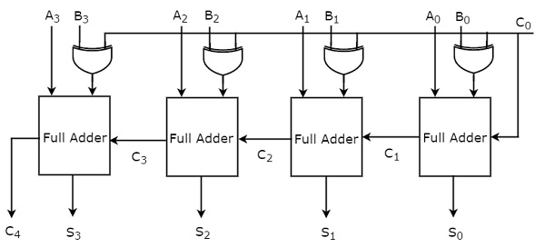
4 bit adder subtractor circuit diagram full#
Then the Boolean expression for a full subtractor is as follows.ĭ = ( X.
4 bit adder subtractor circuit diagram plus#
The two single bit data inputs X (minuend) and Y (subtrahend) the same as before plus an additional Borrow-in ( B-in) input to receive the borrow generated by the subtraction process from a previous stage as shown below.

The main difference between the Full Subtractor and the previous Half Subtractor circuit is that a full subtractor has three inputs. Then we need to produce what is called a “full binary subtractor” circuit to take into account this borrow-in input from a previous circuit. One major disadvantage of the Half Subtractor circuit when used as a binary subtractor, is that there is no provision for a “Borrow-in” from the previous circuit when subtracting multiple data bits from each other. Then all that is needed to convert a half adder to a half subtractor is the inversion of the minuend input X. The two Boolean expressions for the binary subtractor BORROW is also very similar to that for the adders CARRY. If we compare the Boolean expressions of the half subtractor with a half adder, we can see that the two expressions for the SUM (adder) and DIFFERENCE (subtractor) are exactly the same and so they should be because of the Exclusive-OR gate function. Subtracting a “1” from a “1” results in a “0”, but subtracting a “1” from a “0” requires a borrow. As binary notation only has two digits, subtracting a “0” from a “0” or a “1” leaves the result unchanged as 0-0 = 0 and 1-0 = 1. Binary Subtractionīinary Subtraction can take many forms but the rules for subtraction are the same whichever process you use. The subtraction of one binary number from another is exactly the same idea as that for subtracting two decimal numbers but as the binary number system is a Base-2 numbering system which uses “0” and “1” as its two independent digits, large binary numbers which are to be subtracted from each other are therefore represented in terms of “0’s” and “1’s”. Simple school math’s, borrow a 10 if needed, find the difference and return the borrow. This “borrowed” 10 is then return back to the subtrahend of the next column once the difference is found. The complete working with full simulation video can be found in the video linked below.We can not directly subtract 8 from 3 in the first column as 8 is greater than 3, so we have to borrow a 10, the base number, from the next column and add it to the minuend to produce 13 minus 8. The below gif file shows the IC being simulated for all four stages by clubbing in the four input pins of both A and B. Let’s understand a bit more about this IC by using a simulation. Where Ai, Bi and Ci are the input and SUM, Co are the outputs. The block diagram below represents the same.Įach Fuller adder stage will obey the truth table below. The IC also has a Carry Out (CO) pin which will go high if the result has an carry. Based on the values provided to these pins the output Sx will either be high (logic 1) or low (logic 0). The IC has four different stages and each stage has two normal inputs Ax and Bx with an additional carry input called C1. Using the Full Adder IC is pretty much straight forward. It can also be easily cascaded if more than four stages are required. It is a four stage 4-bit counter, meaning it has four individual Full adder circuits each of 4-bit inside a single package.

The CD4008 is a Full Adder with Carry in and Carry out feature. This way the complexity and the BOM cost of the circuit design will greatly go low. Complete Technical Details can be found at the CD4008 datasheet given at the end of this page.Īlthough today we have cheap microcontrollers that could perform all arithmetic operations required for our application, in early days the ICs like Adder, Counter, flip-flops etc were used for same. Note: The Specifications are applicable when the IC is operating at 5V.

Output pin for the Adder circuit (Four pin for four stages) Second Input for the adder circuit (Four pin for four stages)Ĭarry Input - from previous stage if present. It is commonly used in applications where arithmetic operations are involved.įirst Input for the adder circuit (Four pin for four stages) The IC has four independent stages of full adder circuits in a single package. The CD4008 is a high speed, high voltage 4-bit full Adder IC with carry out feature.


 0 kommentar(er)
